BBC Micro/Master Serial Cable
Interfacing a beeb to a PC is sometimes useful if you want to transfer data between the two systems.
The BBC has an RS423 serial port on the rear of the case, but with an unusual 5-pin “domino” layout DIN plug. This carries the following signals:
- Ground
- Data out
- Data in
- RTS (Read to send)
- CTS (Clear to send)
These are electrically compatible with the RS232 port on a PC. However, the suggested wiring in the user guide isn’t quite correct:
Those who require a more complete RS232 connection should try the following:
BBC User Guide page 407
1 Data in to pin 2 (Transmit data)
2 Data out to pin 3 (Receive data)
3 CTS to pin 4 (Request to send)
4 RTS to pin 5 (Clear to send)
5 GND to pin 7 (Signal ground)
This is given in the context of connecting a serial printer with a 25-pin RS232 port. It isn’t how you want to connect to a PC – it won’t work.
A bit of serial terminology is useful here too. RS232 defines the concept of data terminal equipment (DTE) and data communication equipment (DCE). Originally, the standard was used to connect modems (DCEs) to computer teletype terminals (DTEs).
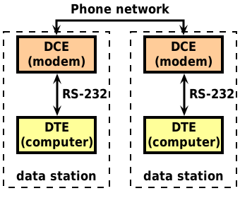
A straight-through male to female cable was used, and all the signal lines are labelled from the point of view of the DTE, so TX data is data going out from the terminal into the modem. On the modem end, the terminology is backwards.
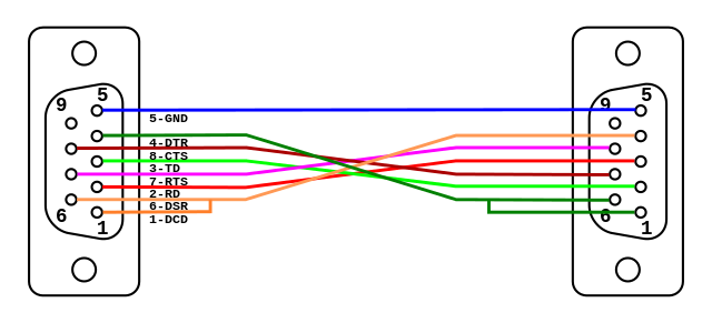
However, we mostly are not interested in connecting modems any more, and are more interested in connecting one computer to another. So the concept of a “null modem” cable is relevant here, which short-cuts the modems and the phone network in the above diagram, allowing the two DTEs to communicate directly.
The most obvious difference here is that the transmit and receive lines must be swapped from one end to the other, ie: TXD must go to RXD at the there end and visa-versa. The handshaking lines are a little more confusing. Here are the commonly used handshaking lines, with the direction being from the DTE point of view.
| Name | Purpose | Direction | DB25/DB9 Pin |
| Data Terminal Ready (DTR) | Computer is ready to receive a connection | Out | 20/4 |
| Data Carrier Detect (DCD) | Modem is connected to remote end | In | 8/1 |
| Data Set Ready (DSR) | Modem is ready to receive and send data | In | 6/6 |
| Request to Send (RTS) | Computer is ready to send data | Out | 4/7 |
| Clear to Send (CTS) | Modem is ready to receive data | In | 5/8 |
RTS and CTS were initially intended for half-duplex modems, where only one modem at a time could transmit. RTS indicates the intention of the computer (DTE) to transmit, and CTS grants permission by the modem (DCE) to do so once it has resynchronised with the remote modem. This is inherently asymmetric, as the DCE is always in control of whether it is sending or receiving. This arrangement is no longer necessary as modems are full-duplex, so RTS is always asserted.
In the late 80s, the meaning of RTS was changed to mean that “the DCE is ready to receive data from the DTE”, and CTS was changed to mean “the DTE is ready to receive data from the DCE”. These signals now operate independently from each other, rather than being a request from the DTE to send, and granting of that request by the DCE.
RTS and CTS should be swapped in a null modem cable, and the actual handshaking is done with the DSR and DTR lines, which should also be crossed. Additionally, DCD and DSR should be tied together at either end so that the carrier detect line is “self asserted”.
As the beeb was made in the mid 80s, the RTS/CTS lines operate more akin to a half-duplex modem, which was the norm when the machine was designed. They’re also the only handshaking lines that the beeb has. In reality, they work far more like the DSR and DTR lines as they follow the original RTS/CTS behaviour from when half-duplex modems were around.
So for a beeb, we need a way of handling the RTS/CTS lines, given that we’re using the beeb’s only handshaking lines for DTR/DSR lines. The answer is simply to tie the RTS and CTS lines at the PC end, so RTS will always assert its own CTS line.
With that knowledge, we can now describe a BBC to PC null modem cable:
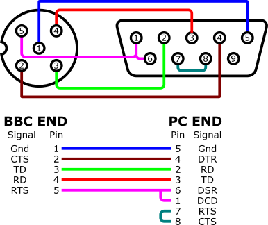
Here, the beeb’s only handshaking lines are used to drive the DTR and DSR lines, and the internal links at the PC end satisfy the DCD and CTS lines needing to be asserted. This arrangement works well for use with XFER to transfer disk images. XFER is particularly useful as it does not require any program to be available on disk or ROM for the beeb – XFER transfers the BBC part of itself directly to the beeb over the serial link.
Questions and comments via this post on Mastodon.